
Below Your Program#
For computers to run complex applications, there needs to be some sort of translation. Computers can only run simple operations; if we were to write the program for example for this website (although a simple application) - we need so much effort and time. This is the idea of abstraction.
There must be some way to convert these high level operations to a low level one. Usually, the bridge between hardware and application software (like this website) is called the systems software. Although, even for application softwares, we have different layers.
A database system runs on top of systems software, and the application runs on top of the database systems.
But let’s get back to systems software. There are many types of systems software, but OS (operating system) and compiler are central to every system.
An OS (like Linux, iOS, and Windows) interfaces between user program and hardware. Some of its functions are:
- Managing input/output operations
- Allocating storage and memory
- Ensuring safe, concurrent use of the computer by multiple applications through protected sharing.
Compilers translate high level languages like C++ or Java to instructions. We talk about this here but Chapter 2 explores this topic more.
Compilers convert english like high level languages, say A + B to assembly language, add A, B. Assembler then convert this to binary or bits which is the alphabet that computers use. They also improve programmer productivity and be independent of the computer they were developed.
Under the Covers#
Now this part is the bulk of this article. We take a look at the 5 classic components: input, output, memory, datapath and control. Datapath and control are sometimes combined to form the processor.
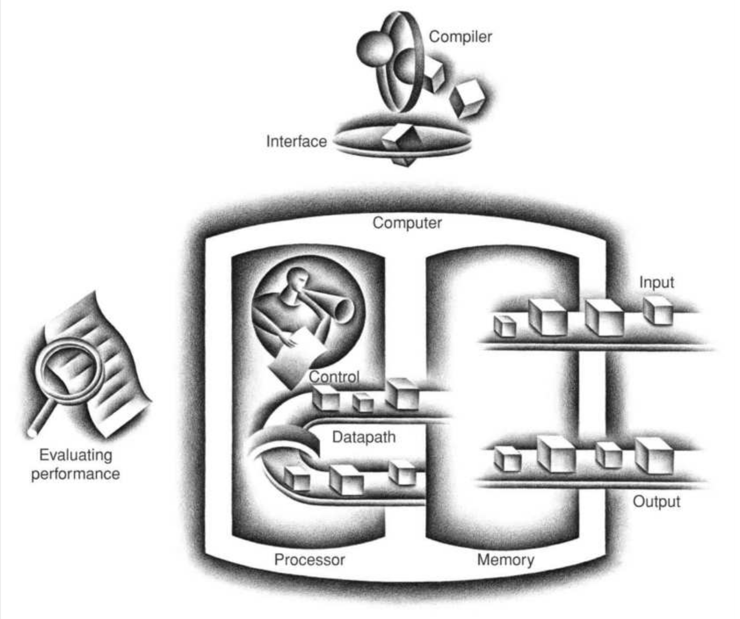
This is a figure from the book. The control sends signals that determine the operations of memory, datapath and input, output. This is what the book refers to as the “BIG PICTURE”. It is a nice way to visualize computer organization because all computers follow this structure.
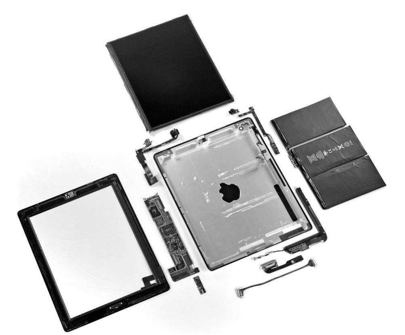
The section here gives us an example: IPad 2. We see the parts laid out as shown above. Here, most of the components are IO.
Input / Output:#
Most PMDs use liquid crystal displays (LCDs). It is made of rod shaped molecules twisted in a helix and control whether to pass light through (not create them). Recent LCD technology has something called “the active matrix” - at every pixel, there is a transistor that controls the current. There are 3 transistors, each controlling the RGB (red, green, blue) color mask that determines the intensity of those colors.
Image is represented as a matrix of bits, 8 bits for each color, and that matrix is called the bit map. The bit map is stored in raster refresh buffer, or frame buffer.
Nowadays, touch screens are replacing normal displays. One common way to implement a touch screen is to use capacitive sensing. Since, people are electrical conductors, transparent conductor is also placed over the glass. And touching distorts the field, changing capacitance.
Datapath And Control:#
The small L-shaped board next to the metal frame is the integrated circuits, more commonly called the chips. This contains the memory and the processor.
“The processor logically comprises two main components: datapath and control, the respective brawn and brain of the processor” (Patterson and Hennessy, 2018, p.74)
Datapath is responsible for the arithmetic operations and control manages what the other components (input, output, datapath and memory) do according to the instructions. This is explored more in Chapter 4.
Here, instruction set architecture (ISA) is formally defined: a bridge between hardware and software where low level systems functions are handled and hidden away from application programmers. ISA along with OS is called the application binary interface (IBA).
Memory is where the programs and data needed by the programs are stored while they are running. It is built from multiple DRAM chips. DRAM stands for dynamic RAM, where RAM means data is accessible in O(1) time as opposed to sequential access memories.
In the processor, there is another type of memory called SRAM. It is a temprorary memory used for caching - a memory where frequently used data is stored. Caches are always checked before accessing the main memory.
But SRAMs and DRAMs are volatile - meaning once the computer is powered off, all data is lost. The solution to that is nonvolatile memory technology. To help distinguish we call the memory while program is running (SRAMs and DRAMs) the main/primary memory and nonvolatile/permanent memory the secondary memory.
Although magnetic disks dominated the secondary memory scene, nowadays we use flash memory. It is even replacing DRAMs in PMDs due to being much cheaper in addition to being nonvolatile. Memory is discussed more in Chapter 5.
The last part of this section discusses communication or computer networks and introduced more key concepts like LANs and WANs.
Technologies for Building Processors and Memory#
This is where we discuss transistors - an electrical component that makes up all our computing devices. We discuss properties of transistors in a different article, but what we need to know right now is that it is a switch that has 2 states: on an off and is controlled by current. They are combined to make memory, logic gates, etc. (You can check out how transistors are used to make SRAM here.)
The technology used in computers first started with a vacuum tube in 1951, but after transistors were made in 1965, we saw an exponential increase. The evolution afterwards is integrated circuit, very large-scale integrated circuit (VLSI), and ultra large-scale integrated circuit (ULSI).
How Are They Actually Made?#
To make these circuits or chips, we start with a silicon wafer—a thin, flat slice of pure crystal. The idea is to draw your design onto the wafer using photolithography, which is kind of like shining light through a stencil to print patterns. The wafer is coated with light-sensitive material, and then a mask (the stencil) is used to shine UV light and “draw” the circuit. After this, we go through a cycle of adding material (like metal or insulators), removing parts we don’t need (etching), and modifying the silicon itself (called doping) to give it the right properties.
This process is repeated many times—layer after layer—to build up the transistors, wires, and all the components needed. Once it’s done, the wafer is cut up into small squares called dies, and each die is tested to see if it works. The working ones are packaged (usually in black rectangular casings with tiny pins or balls underneath) and shipped out for use in phones, laptops, etc. All of this is what people mean when they talk about “chip fabrication” or “semiconductor manufacturing”.
From the author
Thank you for reading this, and special thanks to the authors of the book. Please check out other articles! 😇
References:
Hennessy, J. L., & Patterson, D. A. (2018). Computer Organization and Design: RISC-V Edition (2nd ed.). Morgan Kaufmann/Elsevier.